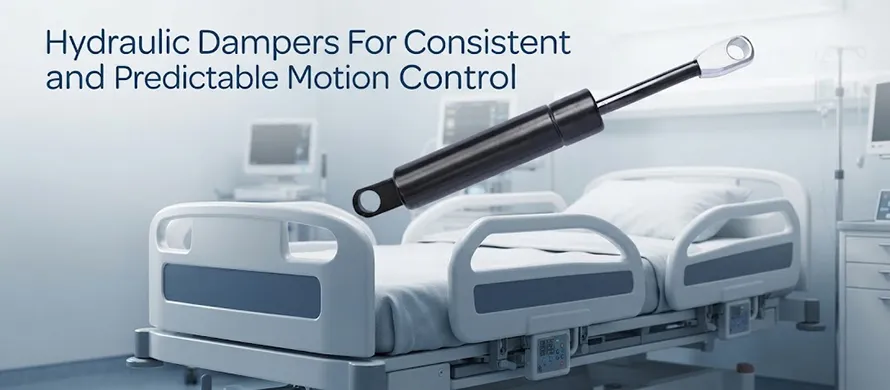
In today’s design language of industrial and consumer products, “motion quality” is rapidly evolving from a nice‑to‑have feature into a critical differentiator of product excellence. Whether it is the smooth raising and lowering of hospital bed side rails or the graceful descent of a pickup truck tailgate, these subtle tactile experiences rely on a seemingly humble yet sophisticated core technology—hydraulic dampers.
At its essence, a hydraulic damper is a device that dissipates mechanical energy. By forcing hydraulic oil through precision‑engineered flow passages, it converts the kinetic energy of moving parts into heat, thereby achieving precise speed control. Unlike gas springs, which use compressed gas to provide lifting or supporting force, hydraulic dampers focus on a single mission: making every motion predictable, smooth, and safe.
This article provides an industry‑wide perspective combined with practical engineering insights, covering the working principles, market landscape, selection criteria, and innovative applications of hydraulic dampers in multiple typical scenarios.
What Is a Hydraulic Damper?
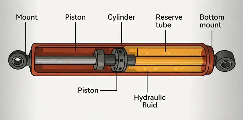
A hydraulic damper is a fully sealed motion‑control component. Its internal construction comprises a pressure tube, a piston rod with a specialised piston system, a damping medium (high‑viscosity hydraulic oil), and precision sealing and guiding assemblies.
When external force drives the piston rod to move inside the cylinder, the hydraulic oil is forced through preset orifices, valves, or specific flow channels in the piston system. The resistance generated as the oil passes through these narrow passages is what we call damping force. This process follows a fundamental physical law—the faster the motion, the higher the shear rate of the oil, and the greater the damping force produced. It is this “speed‑sensitive” characteristic that enables hydraulic dampers to deliver adaptive speed regulation
What Is a Hydraulic Damper?
Although hydraulic dampers and gas springs look quite similar externally—both are slender assemblies of a cylinder and a piston rod—their functional philosophies are fundamentally different:
| Aspect | Hydraulic Damper | Gas Spring |
|---|---|---|
| Primary function | Control motion speed, dissipate kinetic energy | Provide supporting force, assist lifting and balancing |
| Working principle | Oil flow through throttling passages creates fluid resistance | Pressurised gas pushes the piston to generate force |
| Typical objective | Deceleration, cushioning, preventing hard impacts | Effortless opening, load balancing, position holding |
| Internal medium | Hydraulic oil | Inert gas (e.g., nitrogen) |
In real‑world applications, the two often work as a perfect pair: the gas spring “holds” the load, while the hydraulic damper “tunes” the speed, together forming a complete motion‑control solution.
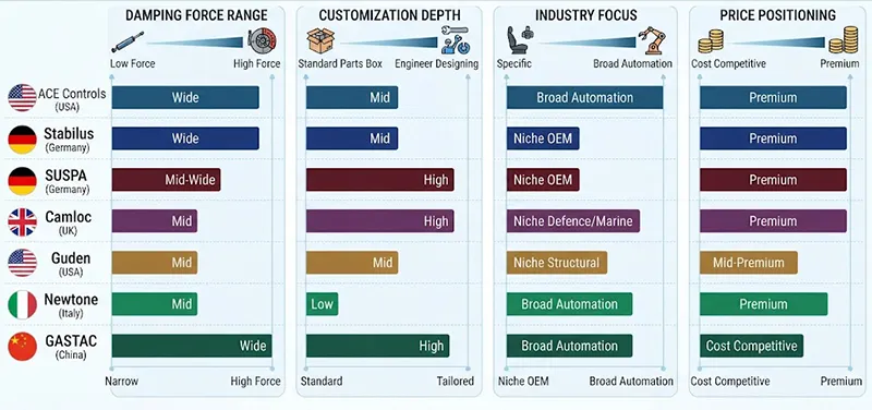
Major Manufacturers of Hydraulic Dampers
After decades of development, the global hydraulic damper industry has formed a competitive landscape led by established European and American technology pioneers and emerging Chinese manufacturing powerhouses. Each major player has its own positioning, technical approach, and strongholds:
Hydraulic Dampers Basic Types
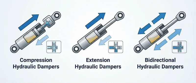
Based on the direction and timing of damping force generation, hydraulic dampers fall into three categories:
- Compression Hydraulic Dampers– When the piston rod is pushed into the cylinder (compression stroke), the system generates the primary damping force. Ideal for controlling “closing,” “lowering,” or “retracting” motions—for example, slow closure of heavy machine hoods to prevent end‑of‑stroke impacts.
- Extension Hydraulic Dampers– When the piston rod is pulled out (extension stroke), the system generates the primary damping force. Suited for “opening,” “raising,” or “extending” motions—for instance, the controlled descent of a pickup tailgate to avoid rapid free‑fall.
- Bidirectional Hydraulic Dampers – Damping force is produced in both compression and extension strokes. Necessary when full‑stroke speed control is required—such as hospital bed side rails, where both raising and lowering must be smooth and steady.
Some high‑end products also offer adjustable hydraulic dampers, allowing end‑users or production engineers to fine‑tune the damping force on‑site according to actual load and speed requirements, greatly improving versatility and fault tolerance.
Basic Selection Guide for Hydraulic Dampers
A common misconception in engineering practice is to “select a damper based on component weight.” In reality, the professional approach follows a core principle: choose the damper according to the motion direction and speed that need to be controlled, not merely by the mass of the load. The following key variables must be verified in the selection process:
- Target damping direction: compression, extension, or both?
- Effective mass and inertia of the moving part – determines the energy to be dissipated.
- Effective stroke – does the required linear travel match the damper stroke?
- Desired motion speed – what is the expected closing or opening time? This dictates the required damping force.
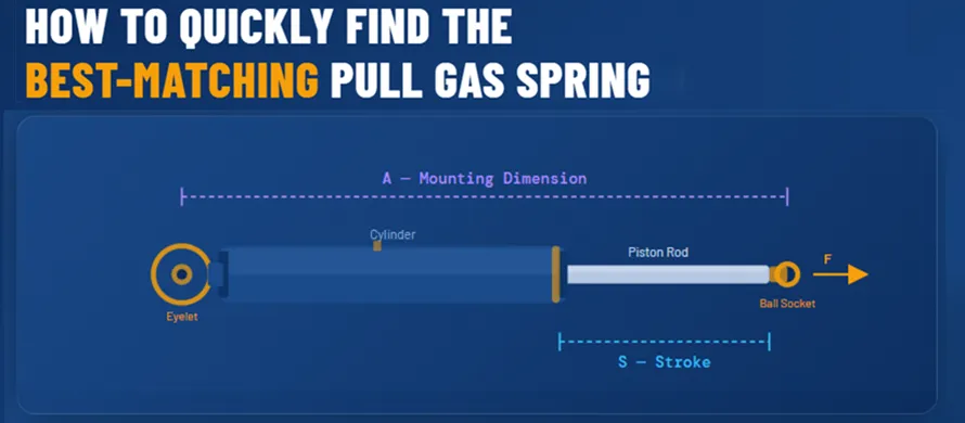
- Mounting geometry and interfaces – are the available space, attachment points, and connection methods compatible?
- Service environment – temperature range, humidity, corrosive media, or dust exposure?
Six Typical Applications of Hydraulic Dampers
The application boundaries of hydraulic dampers are far broader than most people imagine. The following six scenarios span healthcare, outdoor mobility, commercial vehicles, and premium consumer details:
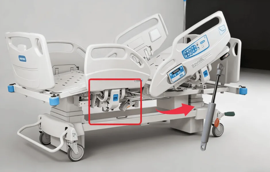
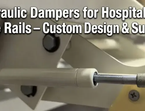
1. Hospital Bed Side Rails
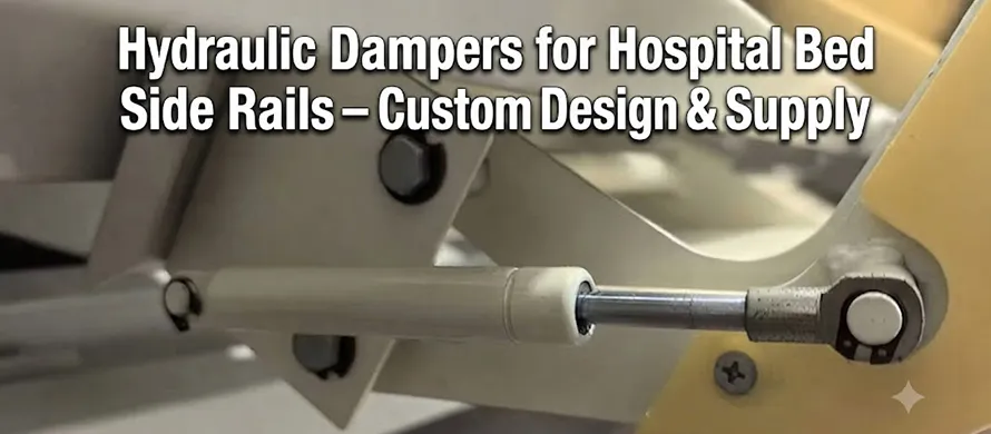
In intensive care and daily nursing, the raising and lowering of bed side rails directly affect patient safety and caregiver efficiency. If a side rail drops too quickly, it not only creates disturbing impact noise but also poses a serious risk of pinching patient limbs or caregiver fingers.
Solution: Integrate a bidirectional hydraulic damper into the rail hinge mechanism. When the rail is released, the damper generates smooth resistance on the compression stroke, forcing the rail to descend at a uniform, slow speed. Even if the operator pushes downward forcefully, the damper’s speed‑sensitive mechanism automatically increases resistance to prevent “free‑fall.” This approach has been widely validated by leading global medical bed brands.

2. Hitch Bike Racks
When a hitch‑mounted bike rack is fully loaded with several bicycles weighing up to dozens of kilograms, enabling an average‑sized adult to easily fold it up or tilt it down presents a significant ergonomic challenge.
Solution: Incorporate a bidirectional tilt‑assist damping system. The damper provides controlled resistance in both upward and downward motions—cushioning the descent and offering balancing torque during lifting to offset part of the gravitational moment. Premium rack brands have widely adopted this technical approach.

3. Utility Trailers
Tilt‑bed utility trailers use gravity to assist loading and unloading, greatly improving efficiency on construction sites, farms, and gardens. However, if the tilting platform flips unrestrained under gravity, it creates violent hard impacts that can damage cargo or even deform the trailer structure.
Solution: Install hydraulic damping systems in parallel with the tilt mechanism. When the platform begins to tilt, the dampers intervene to absorb the gravitational potential energy of the platform and load, converting it into heat and dissipating it slowly. This results in a “fast yet controlled, smooth stopping” dumping action. During transport, the dampers also attenuate road‑induced bounce and sway, improving stability.
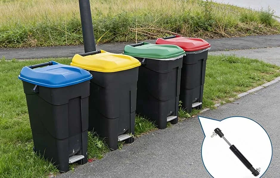
4. Clinical Waste Bins
Medical environments have extremely strict requirements for noise levels and infection control. A bin lid that slams shut not only produces annoying impact noise but can also disturb airborne dust or aerosols carrying pathogens.
Solution: Install a single‑acting or bidirectional damper at the lid pivot. The opening direction offers minimal resistance to allow quick waste disposal, while upon release, the damper provides sufficient resistance in the closing direction to drive the lid to close slowly and silently. This technical solution has seen mature adoption in European and American medical equipment markets.
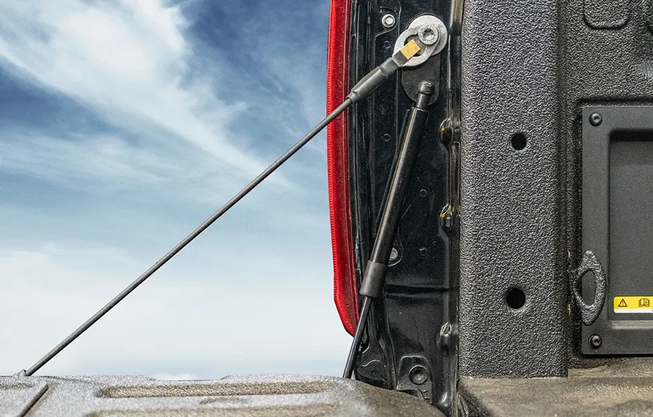
5. Pickup Truck Tailgates
Pickup tailgates are typically heavy sheet‑metal structures. If released directly, the tailgate will fall rapidly under gravity. This hard impact not only generates loud noise but also accelerates hinge wear over time and poses a risk of injuring the operator’s feet or lower legs.
Solution: Add a hydraulic tailgate‑assist damper. This damper produces a continuous, uniform damping force in the extension direction, absorbing the gravitational potential energy of the tailgate. Whether the operator releases it or pushes it down, the damper’s speed‑sensitive behaviour keeps the descent speed within a safe threshold. This product category has become a popular aftermarket upgrade for pickups.
GASTAC Hydraulic Damper Specifications and Model Selection Table
For the three damping types described above, GASTAC has built a comprehensive product matrix to meet cross‑industry needs, from precision electronics to heavy machinery. The core platform is the compact and efficient 6‑15 size (6 mm piston rod diameter, 15 mm cylinder diameter), with damping force ranging from 40 N to 250 N and strokes from 12 mm to 160 mm. In addition, GASTAC offers a wider selection of cylinder diameters (12, 15, 18, 22, 24, 28 mm) and piston rod diameters (4, 6, 8, 10, 12, 14 mm) to suit diverse applications.

Hydraulic Dampers General Specification Range
| Specification Parameter | Standard Industrial Range |
|---|---|
| Piston Rod Diameter | Ø 6 mm to Ø 14 mm (0.24 in to 0.55 in) |
| Outer Body Diameter | Ø 15 mm to Ø 40 mm (0.59 in to 1.57 in) |
| Stroke Length | 10 mm to 800 mm (0.4 in to 31.5 in) |
| Damping/Extension Force | 20 N to 10,000 N (4.5 to 2,248 lbf) |
| Cycle Life Expectancy | 100,000 to 300,000 cycles |
| Operating Temperature | -4°F to 176°F (-20°C to +80°C) |
All Type Hydraulic Dampers Size Chart
Designed for controlling “closing,” “lowering,” or “retracting” motions. When the piston rod is pushed into the cylinder, the internal throttling system generates the preset damping force.
Designed for controlling “opening,” “raising,” or “extending” motions. When the piston rod is pulled out, the internal valve system builds backpressure in the tensile direction to generate damping force.
| ID Code | Stroke | Extended | Compressed | Force | Rod Dia. | Body Dia. | Thread Size |
|---|---|---|---|---|---|---|---|
| HD010053 | 1" | 5.3" | 4.3" | 112 | 0.24" | 0.59" | M5 × 0.8 mm |
| HD020073 | 2" | 7.3" | 5.3" | 112 | 0.24" | 0.59" | M5 × 0.8 mm |
| HD020083 | 2" | 8.3" | 6.3" | 270 | 0.31" | 0.87" | M8 × 1.25 mm |
| HD030092 | 3" | 9.2" | 6.3" | 112 | 0.24" | 0.59" | M5 × 0.8 mm |
| HD039122 | 3.9" | 12.2" | 8.3" | 270 | 0.31" | 0.87" | M8 × 1.25 mm |
| HD039126 | 3.9" | 12.6" | 8.7" | 270 | 0.39" | 1.1" | M8 × 1.25 mm |
| HD059161 | 5.9" | 16.1" | 10.2" | 270 | 0.31" | 0.87" | M8 × 1.25 mm |
| HD059165 | 5.9" | 16.5" | 10.6" | 270 | 0.39" | 1.1" | M8 × 1.25 mm |
| HD079205 | 7.9" | 20.5" | 12.6" | 270 | 0.39" | 1.1" | M8 × 1.25 mm |
| HD079222 | 7.9" | 22.2" | 14.4" | 720 | 0.55" | 1.57" | M14 × 1.5 mm |
| HD098244 | 9.8" | 24.4" | 14.6" | 270 | 0.39" | 1.1" | M8 × 1.25 mm |
| HD118283 | 11.8" | 28.3" | 16.5" | 270 | 0.39" | 1.1" | M8 × 1.25 mm |
| HD118301 | 11.8" | 30.1" | 18.3" | 720 | 0.55" | 1.57" | M14 × 1.5 mm |
Five Key Considerations When Selecting a Hydraulic Damper
Drawing on technical literature and engineering experience from leading manufacturers, selection decisions should be systematically evaluated across five dimensions:
- Precisely define the damping direction. This is the first and most error‑prone step. You must clearly answer which stroke—compression, extension, or both—needs to be controlled. An incorrect direction will render the damper completely ineffective.
- Rigorously match damping force with load. Damping force is neither maximised nor minimised—it must be engineered based on the moving part’s mass, desired speed, and lever arm geometry. The key is “matching,” not oversizing.
- Determine the appropriate stroke and mounting dimensions. The stroke must cover the full range of motion, while both extended and compressed lengths must fit within the available space. An overly long stroke creates unnecessary protrusion; too short a stroke will not cover the required travel.
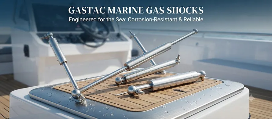
- Assess environmental adaptability and durability. Will the product operate in extreme cold or high heat? Is it exposed to coastal salt spray or industrial acids/alkalis? Reputable manufacturers can supply corrosion‑resistant finishes and wide‑temperature sealing solutions as required.
- Confirm maintenance and installation attributes. The industry standard is “fully sealed, maintenance‑free, ready‑to‑install.” A quality damper should never require oil refills or seal replacements over its entire service life. Verify this feature to minimise downstream maintenance costs.
Conclusion
Hydraulic dampers are undoubtedly the “quiet yet indispensable” functional components of modern industrial and consumer products. They rarely appear in prominent product advertisements, yet they profoundly shape the physical feel and safety margin of every opening, closing, and folding motion.
GASTAC, as China’s No.1 hydraulic damper manufacturer, leverages its solid precision‑manufacturing foundation, comprehensive quality certifications, and flexible customisation capabilities to continuously deliver high‑quality, high‑reliability motion‑control solutions to OEM customers and end‑markets worldwide. Whether in life‑critical medical equipment, experience‑driven outdoor gear, or heavy‑duty industrial machinery, GASTAC empowers customers to build safer, more comfortable, and more competitively refined products through superior engineering execution.
Stay in the loop